Background
Our series 4 weapon idea was conceived by Bryan and Richard from the workshop at work. The pneumatic spike, or pneumatic toothpick as it unfortunately became known, proved an utterly reliable and powerful weapon 1) when run at its design pressure and 2) we remembered to bolt everything together properly... Unfortunately this situation only happened in testing and at the first Debenham charity event we attended. Mentorn had issues with our high pressure piping, thus what you saw on TV is nowhere near what it could actually do. Make sure that everything in your pneumatics system is rated for the pressure it is running at...
Over to Bryan...
Disclaimer
Pneumatic systems can be extremely dangerous and should only be constructed by competent persons. The information in this document is meant as a guide only and is used at your own risk.
Basic Principle
The gas source is a pressure certified tank filled to a pressure of 1000psi. This pressure is then regulated to 10 bar for the main system. Activating the control valve transfers this pressure to the back of the ram, causing it to extend. De-activation of the control valve transfers the pressure to the other side of the ram, causing it to retract.
The Components
Main gas supply
There are a number of suitable options available for this e.g. CO2 fire extinguishers or Soda Stream Cylinders. We used a pair of oxygen cylinders supplied by Life Support Engineering. Two were needed to overcome size restrictions within the robot. The original plan was to use welding gas cylinders, but these were deemed unsuitable by Mentorn. If your cylinder is not rated to a sufficiently high pressure, it may explode. We used Nitrogen in testing, compressed air at the filming, and Argoshield (because we had bought some for welding!) at Debenham.
High Pressure Relief Valve
The most readily available option is a disc type burst valve. These are built into fire extinguishers, and so are easily available from both the manufacturers, and extinguisher service companies. Unless you are using a fire extinguisher as your main tank, these can be difficult to fit, and as such, we only used this type of device as an emergency spare. An alternative is the type of pressure relief valve used on gas regulators. These are far more difficult to get since modern regulators don't normally have these on the high pressure supply. This was our preferred option, and we were fortunate enough to find one rated at about 1250psi.
Main Supply Shut Off Tap
It is essential that one of these be fitted, so the main system can be isolated from the supply. Pneumatic control taps are rarely rated above 300psi, and so are not suitable. Hydraulic control taps are generally more suitable being rated at 4000psi or higher. The most easily available are ball valves.
Regulator
Flow rate and output pressure must be considered for this component. Many commercially available regulators are only rated to ~75psi, or are designed to give low flow rates (e.g. welding regulators.) We used a custom built regulator made by GasArc and supplied by our local plant hire company. The size of our regulator was reduced quite considerably by the removal of the plastic control knob, though this does make it quite difficult to adjust.
Distribution Manifold
This is not essential, but does tidy up the plumbing quite considerably. The one we used was made of an aluminium alloy, and was substantially lighter than the T-pieces and 4-way adaptors that we would have needed without it. We bought ours from J&L Industrial.
Venting Tap
Another essential piece of safety kit. It is similar to the Main Supply Shut Off Tap, but need not be rated to such high pressure, as it operates on the low pressure side only.
Pressure Relief Valve
This gives some protection against regulator failure by venting any excess pressure to atmosphere. Various commercial items are available, but we used one off the low pressure side of an old regulator.
Reservoir
This acts as a buffer tank for the system. Various purpose built items are available, but the most convenient item that we (and many other teams) have found is a dry powder fire extinguisher. Ours were bought from Halfords.
Control Valve
The simplest way of controlling a double acting ram is a five port solenoid operated valve. Remember to pick a solenoid voltage compatible with your robot (I know this may seem a bit obvious, but I have seen someone put a 12V dc valve in a 240V ac system before now.) We used a 12V dc valve with a ballast resistor.
Fast Exhaust Valve
Basically a way to get the gas out of the venting side of the ram quickly. Unless you are pre-venting your ram, these inexpensive components are definitely worth including the extra weight for.
Ram
The Business end of the pneumatic system. Since some robots get their weapon stuck in other robots, we decided to use a double acting cylinder (gas powered in both directions.) Single acting cylinders have another disadvantage in that the spring return on them reduces the force that can be applied.
Exhaust Diffuser
This is simply a device to ensure that fast flowing gas cannot come into contact with your hand when venting the system. It is not advisable to fit these anywhere other than on the system vent, since they also reduce flow.
Flow Restrictor
These simple reduce flow rate of the gas in the circuit beyond them. We used them on the system vent and the retract exhaust. Whilst many purpose built items are available, we found that a piece of small bore tubing was sufficient for our purposes.
Connectors
We used a mixture of push fit and hose tails. In areas where high flow rates were important, we used brass hose tails with half inch bore pipe. In low flow areas, we used 4mm tube and push fits.
Diagram
Circuit Construction
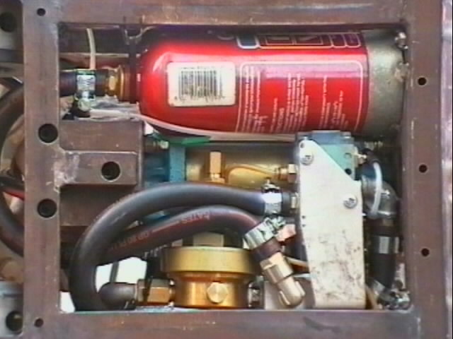
The Main Gas Supply tanks are connected together using metal pipework. If using dual tanks, this makes removal, refitting and charging easier. The High Pressure Relief Valve is fitted to a spur on the pipework, in such a way that escaping gas will not hit anyone holding the tanks. The Main Supply Shut Off Tap is attached to this, and is the last component in the 'hard plumbed' section. A high pressure (hydralic) hose is then attached between the tap and a removable pipe fitting. (This allows disconnection of the system for charging.) High pressure (hydralic) hose is again used, to attach the second part of the removable fitting to the regulator. (Editors Note: It is this part of our system that Mentorn had issues with. We advise that you use proper high pressure sleeved hydralic connectors with properly rated hydralic hose for this part of the system. If you need more than one main gas storage tank, build a metal frame to hold them. NEVER weld to the tank itself, as you could weaken it to the point where it will explode!)
 The outlet of the regulator is then connected to a manifold. In our case it was screwed directly onto the ¼BSP fitting supplied on the regulator. The Pressure Relief valve is screwed directly into the manifold, ideally opposite the regulator. Also connected to the manifold are the Control Valve supply, the Reservoir and the Venting Tap. The Venting Tap is connected using 4mm push fit, giving a flow restriction, and so effectively reducing the outlet pressure. An Exhaust Diffuser is screwed directly into the outlet side of the Venting Tap. By sandwiching a metal plate in this joint, it also served as a mounting for the tap.
The Reservoir is attached to the manifold using ½" bore tubing and brass hose tails (a special brass cap was made from the extinguisher handle and screwed into the fire extinguisher to allow BSP fittings to be attached). ½" bore tubing and brass hose tails are also used to attach the Control Valve supply to the Manifold (this connection should be as short as possible). The extend exhaust of the Control Valve is left vented directly to atmosphere (nothing should come out of it since there is a fast exhaust valve in the system). The retract exhaust on the Control Valve is connected to the cooling inlets on the drive motors via 4mm pipe and push fit connectors.
The extend outlet on the Control Valve is connected to the back of the ram using ½" bore tubing and brass hose tails (this connection should be as short as possible). The retract outlet of the Control Valve is connected to the inlet of the Fast Exhaust, using 4mm tubing and push fit connectors (the retract speed is not critical, and so the opportunity to save some weight was taken). The cylinder connection of the Fast Exhaust is connected to the front of the Ram using a very short piece of metal piping. The exhaust port on the Fast Exhaust is left open to the atmosphere.
Testing
Before assembly into the robot, the system was assembled on the bench for testing. This system was not identical to that used in that pressure gauges were inserted at key points. Initial tests were also plumbed using small bore push fit connectors, chosen because they allow easy tapping into the system and the tubing will fail before any of the mechanical components. First trials were carried out at approximately 4 bar, this being the minimum operating pressure for most of the components used, and the pressure gradually increased from there to the final operating pressure. This testing showed up an unexpected problem. Because the system was using a non-lubricated gas supply, the valve and the fast exhaust were found to stick. Be sure to lubricate all moving parts well before the system is assembled. This is easily achieved by running a few drops of oil into the ports of the components.
Since we used mainly second hand components, ours were stripped down and overhauled before use, and all sliding surfaces were greased prior to assembly. I wouldn't advise doing this unless you really, really know what you are doing control valves are not as simple as they look and the seals and other components can be extremely delicate (the valve we used contained some small brass cages that could be easily crushed or distorted by hand).
If using a fast exhaust valve, don't be surprised if you get quite a loud bang when you fire the ram. This is completely normal, and is just the plunger moving. In all testing, the ram should be secured to the bench (we held it in a vice be careful not to damage it) and the system should be operated from a safe distance even broken pipes can do a lot of damage!
Leaks (Editors Footnote #1)
It is a very good idea to make absolutely sure that your completed system does not leak. At the filming you can spend a long time waiting to go on after being charged, and then it can be quite a few minutes again between switch on and the start of your fight. We used a spray soap solution (diluted washing up liquid will do) to find any leaks, as it bubbled where they were present. PTFE tape was applied to all joints as a matter of course, while it was necessary to use an epoxy seal in some places also.
Update (Editors Footnote #2)
Since the start of 2002, the Robot Wars rules on pneumatic systems have been significantly tightened, according to advice from the HSE. Only a few particular sizes of main resevoir tank are allowed, and the bottle must be completely removable in less than five minutes (a cage is provided backstage for this purpose). All resevoir tanks used must be in good condition and must be stamped with a recent test date. It is extremely important to ensure your design can comply with these rules - make sure you know what the rules allow before you start building!
Mail Bryan at helicalscan@supanet.com with any questions or comments, however for safety reasons he may be unwilling to advise novice pneumatics users.